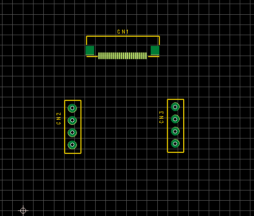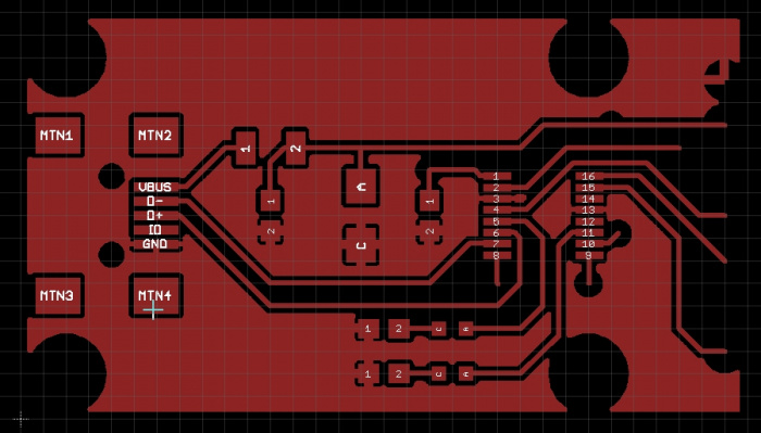

The image below shows the dialog you'll use to select units, file format, and layers for export.


After you create a new Gerber output option, you'll need to configure what information is exported with each of these options.

In the above image, the 'Backdrill Gerbers' entry and the 'Gerber Files' entry are both in RS-274X format, but these options will create PCB Gerber files for different layer sets. Note that you can create multiple sets of Gerber outputs. Use an OutJob file to generate Gerber files. To create a new export option for Gerber X2 files, right-click in the 'Fabrication Outputs' area and select the Gerber X2 entry. An option has been created for Gerber RS-274X files and specifically for backdrilled layers. The image below shows an OutJob file with multiple options enabled for different sets of manufacturing documentation. Once this is created, you can start configuring which manufacturing files you need to generate, as well as the file formats you want. To get started generating PCB Gerber files, add a new OutJob file to your PCB project. However, once you've setup the options in your OutJob file for your project, you can regenerate manufacturing deliverables whenever you want. Some of these documents can be generated quite easily from an OutJob file in Altium Designer, while others require a few steps to setup. Information in mechanical layers, such as a drill table, stackup diagram, and any dimensions.Drill hit locations, which are can be delineated by plated vs.Pad locations for application of solder paste.Although they aren't visible above, they include many important pieces of information: These other layers include more information than is shown in the above image. Note that there are additional files for other layers, which will be generated when you create your Gerber files. Here, only the silkscreen layer and copper features on the top layer are visible.Ī preview of what our final PCB Gerber file will look like. The image below shows two layers from the above PCB layout. When you create PCB Gerber files, information in each layer will be saved in its own file, and these files can be loaded into a new CAM document for inspection. The image below shows the PCB layout above translated into Gerber files and viewed in the CAMtastic viewer. Pick-and-place files for automated assembly.STEP files for importing your board into a mechanical design program.
ALTIUM DESIGNER PCB MIRROR PDF
ALTIUM DESIGNER PCB MIRROR HOW TO
In this article, we'll guide you through this process of how to make PCB Gerber files and show some example tasks you might need to perform to generate them. Altium Designer helps make the process for generating Gerber files quick and easy without forcing you to use an external program. When you're ready to create your Gerber files, you need the right set of CAM processor tools that can take data from your PCB layout. These files are used by PCB manufacturers to prepare stencils for photoresist exposure and subsequent etching. Once you've got your PCB layout finished and you're ready to start preparing for manufacturing, one of the critical steps is to create PCB Gerber files.


 0 kommentar(er)
